World as 3D model
Last Update: 26.03.2025Using a resin printer I wanted to create a model of earth, as detailed as possible, printed in reasonable time. 3D models I found only were mostly in a very rough resolution. Some that were detailed also included the height information from the seas, which I did not want to be shown in the print.
So I got my hands onto the GIS data from GMTED2010 again and created a 3D model using QGIS and Blender.
Export a height map from GIS data
In QGIS I imported the GMTED2010 data using the ds75_grd variant as raster layer in a new project using Layer -> Add Layer -> Add Raster Layer ... and selecting the ds75_grd/prj.adf as source.
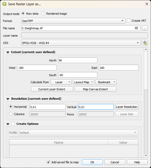
Then I opened up the context menu on this imported layer, to go to Export -> Save As ... and export a height map as GeoTIFF file. A GeoTIFF file is still a TIFF file, so it can be used as height map.
With this I had a plane image of earth with height information and could move to the 3D modelling part.
Create the base (plane) 3D model using Blender
To map a plane on a sphere I needed to do the reverse coordinate transformation as usually done for GIS data.
So, I started Blender, delete everything in the initial setup (Hint: a, x, delete) and created a plane (Shift+A, Plane). Then I switched to Edit Mode (Tab) and subdivided the mesh 100x to get a higher resolution (Menu: Edge -> Subdivide, set Number of Cuts to 100). Then I subdivided the whole mesh again 10x. So, I now had a reasonable high dense plane to apply the height map to.
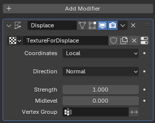
To get the height information to the mesh I switched back to Object Mode (Tab) and added a Displace modifier to the plane. There I create a new texture by clicking on New besides the texture icon and opened the TIFF file I created before.
This gave me the basic mesh I wanted, but the height displacement was not as high as I wanted it:
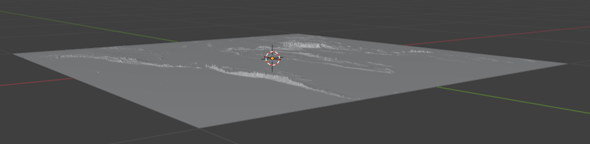
So, I increased the Strength in the displace modifier to 2.
Create the sphere based on the plane 3D model using Blender
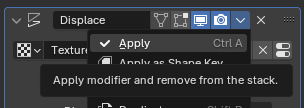
Using the displaced plane the next step is to apply the displacement, so the mesh is fixed for the following geometrical transformations.
Now the plane can be transformed to a sphere using the Warp transformation. To do this I first switched to Edit Mode of the plane and selected all vertices (Hint: a). Then I moved all vertices up the Z axis by 1 (the radius of the sphere, Hint: g, z, 1, enter).
The next steps are two warp transformations, which must be done in correct order to not distort the geometry. The height map has information from “left-to-right” of 360 degrees and from “top-to-bottom” of the map of 180 degrees. This defines the warps needed to get the sphere.
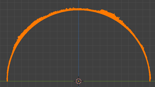
First, I aligned the viewport so that I view the “top-to-bottom” line from the side. In my case this was the “Right Orthographic” view (Hint: 3).
Still in Edit Mode and all vertices selected I did the first warp in the menu (Mesh -> Transform -> Warp) and set the angle to 180 degrees.
From here I switched/rotate my view to the “left-to-right” side, so the “Front Orthographic” view (Hint: 1). From here I created the second warp via the menu and set the angle to the now corresponding angle of 360 degrees. After switching back to object mode, I now had a nice 3D mesh model of earth.
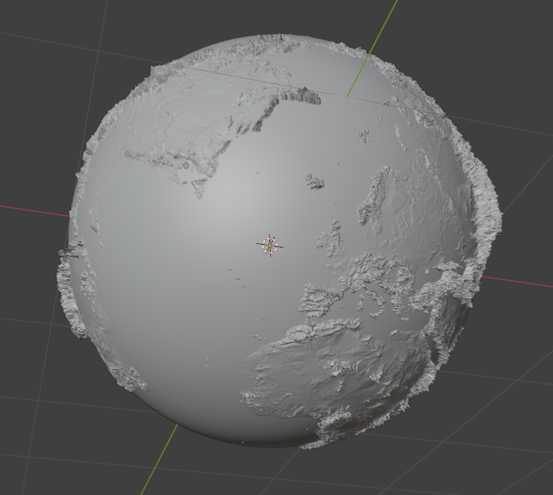
I used this model to print a small 3cm diameter resin sphere and published it on printables: 3D Model